
AS 8 TC - Professional audio equipment AKG - Free user manual and instructions
Find the device manual for free AS 8 TC AKG in PDF.

| Product type | 8-channel automatic audio mixer |
| Brand | AKG |
| Model | AS 8 TC |
| Form factor | 19-inch, 1U rack-mountable |
| Number of channels | 8 balanced microphone/line inputs |
| Power supply | 20 VAC power adapter included |
| Power consumption | Variable (adapter always consumes a little even when off) |
| Tone control | Yes (AS 8 TC): separate treble (HF) and bass (LF) control per channel |
| Operating mode | Manual (DIRECT) or automatic (AUTO) per channel |
| Phantom power | +15V per channel, switchable (DIP 2) |
| Input gain | 0 dB, +30 dB or +60 dB per channel (DIP 3 and 4) |
| Compressor/Leveler | Built-in, with threshold (THRESHOLD) from 0 to -40 dB |
| Main outputs | Balanced MAIN OUT |
| Direct outputs | Unbalanced DIR. OUT per channel |
| Control interface | RS-232 for LecNet software (CD-ROM included) |
| External control | 15-pin Sub-D connector for potentiometers, switches or DC voltage |
| Daisy chaining | Possible via EXPANSION IN/OUT for more than 8 channels |
| Cleaning | Slightly damp cloth, unplug before cleaning |
| Safety | Do not expose to moisture, heat, shocks; do not open, user-serviceable parts inside |
| Country of origin | (Not specified) |
| Included accessories | Power adapter, RS-232 cable, LecNet expansion cable, software CD-ROM |
| Intended use | Professional sound reinforcement, conferences, multi-purpose rooms |
Frequently Asked Questions - AS 8 TC AKG
User questions about AS 8 TC AKG
0 question about this device. Answer the ones you know or ask your own.
Ask a new question about this device
Download the instructions for your Professional audio equipment in PDF format for free! Find your manual AS 8 TC - AKG and take your electronic device back in hand. On this page are published all the documents necessary for the use of your device. AS 8 TC by AKG.
USER MANUAL AS 8 TC AKG
Please read the manual before using the equipment!
- Do not spill any liquids on the equipment and do not drop any objects through the ventilation slots in the equipment.
- The equipment may be used in dry rooms only.
- The equipment may be opened, serviced, and repaired by authorized personnel only. the equipment contains no user-serviceable parts.
- Before connecting the equipment to power, check that the AC mains voltage stated on the supplied AC adapter is identical to the AC mains voltage available where you will use the equipment.
- Operate the equipment with the supplied 20-V AC adapter. Using adapters with a DC output and/or a different output voltage may cause serious damage to the unit.
- If any solid object or liquid penetrates into the equipment, shut down the sound system immediately. Disconnect the AC adapter from the power outlet immediately and have the equipment checked by AKG service personnel.
- If you will not use the equipment for a long period of time, disconnect the AC adapter from the power outlet. Please note that the equipment will not be fully isolated from power when you set the power switch to OFF.
- Do not place the equipment near heat sources such as radiators, heating ducts, or amplifiers, etc. and do not expose it to direct sunlight, excessive dust, moisture, rain, mechanical vibrations, or shock.
- To avoid hum or interference, route all audio lines, particularly those connected to the microphone inputs, away from power lines of any type. If you use cable ducts, be sure to use separate ducts for the audio lines.
- Clean the equipment with a moistened (not wet) cloth only. Be sure to disconnect the AC adapter from the power outlet before cleaning the equipment! Never use caustic or scouring cleaners or cleaning agents containing alcohol or solvents since these may damage the enamel and plastic parts.
-
Use the equipment for the applications described in this manual only. AKG cannot accept any liability for damages resulting from improper handling or misuse.
-
The AC adapter will draw a small amount of current even when the equipment is switched off. To save energy, disconnect the AC adapter from the power outlet if you will leave the equipment unused for a long period of time.
- When scrapping the equipment, separate the case, circuit boards, and cables, and dispose of all components in accordance with local waste disposal rules.
1.1 Safety
1.2 Environment
2 Description

The AKG AS 8 is an 8-channel, single rack space automatic audio mixer. Using a unique mixing algorithm, the automatic mixing action is inaudible and very simple to set up. The AS 8 offers a range of remote control options including an RS-232 port. In addition, the AS 8 is equipped with a sophisticated compressor/leveller for dynamic range control. Multiple AS 8s can be coupled together for applications that call for more than eight microphone channels.
The AS 8 TC is identical to the AS 8 and provides separate HF and LF controls on each channel.
For more details refer to the AS 8 / AS 8 TC Owner's Manual.
1xAS8orAS8TC
1 x AC adapter
1 x CD-ROM with "LecNet for AKG" software
1 x RS-232 cable
1 x LecNet expansion cable
2.1 Introduction
2.2 Packing List
3 Installation and Interfacing

- Install the unit in your 19" rack.
- If you use only one unit, set the MASTER/SLAVE switch to "MASTER".
If you need more than eight microphone channels, you can couple several AS 8s /AS 8 TCs together.
- Set the MASTER/SLAVE switch on the unit in the highest slot in the rack to "MASTER".
- Set the MASTER/SLAVE switches on all other units to "SLAVE".
- Use the supplied LecNet expansion cable to connect the EXPANSION IN port on the "Master" to the EXPANSION OUT port on the first "Slave" and so on as shown in fig. 1.

Fig. 1: Daisy-chaining several AS 8s
3.1 Rack Mounting
3.2 Daisy Chaining
3.3 Audio Connections
- Connect your microphones and other audio sources to the CH 1 IN to CH 8 IN audio input terminals. All inputs are balanced. To connect unbalanced audio sources, connect the signal lead to the "+" terminal and the shield to both the "-" and ground terminals.
- If you use condenser microphones, check what supply voltage or what type of power supply they require. If your condenser microphones will operate on +15V phantom power, set the rear panel dip switch no. 2 for the appropriate channel(s) to ON to switch phantom power for each condenser microphone on.
- Connect the MAIN OUT terminals to the amplifier input. The output is balanced. To connect to an unbalanced inputs, connect the hot wire of the cable to the "+" terminal and the shield to ground. Leave the "-" terminal floating!

Important!
Each audio channel provides an unbalanced direct output called DIR. OUT. If you use the DIR. OUT terminals as additional outputs, DO NOT connect the ground lead (shield) of the cable to the ground terminal of the respective input but to the ground terminal of the MAIN OUT.
3.4 Connecting to the Computer
Use the supplied RS-232 cable to connect the RS-232 port on the AS 8 / AS 8 TC rear panel to the RS-232 port on your computer.
3.5 Connecting Remote Level Controls
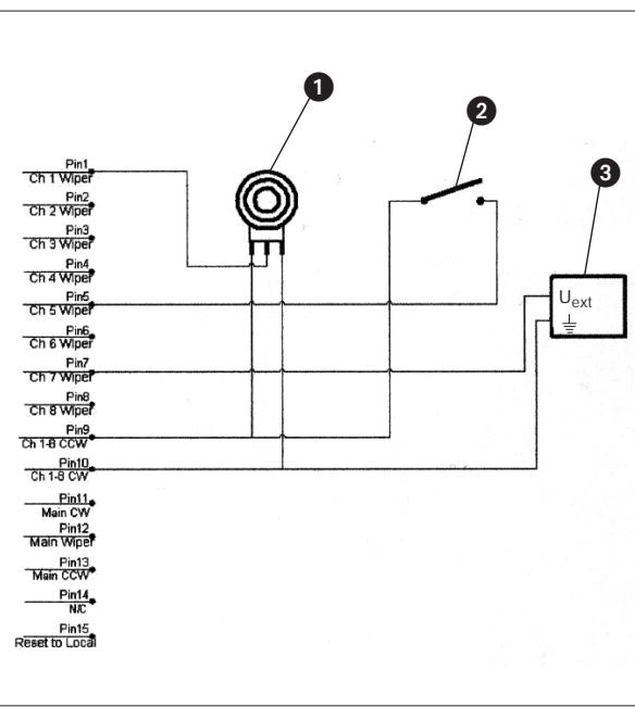
Fig. 2 shows three examples:
The REMOTE LEVEL CONTROL 15-pin D-Sub connector on the rear panel of the unit allows you to control the level of each channel separately or to mute channels individually. Depending on the application, you can use potentiometers, switches, or external control voltages.
1 Continuous level control of channel 1 using a 10k linear pot.
2 Muting channel 5 with an SPST switch.
3 continuous level control of channel 7 using an external DC control voltage (U_ext = control voltage, 1三 = ground).
3.6 Connecting to Power
- Connect the cable on the supplied AC adapter to the PWR IN jack on the AS 8 / AS 8 TC rear panel.
- Connect the AC adapter to a convenient power outlet.

Fig. 2: Remote level control example.
4 Operating Notes
4.1 Local Mode
You can set up and operate your AS 8 / AS 8 TC either in Remote mode from a computer or in Local mode using the controls on the AS 8 / AS 8 TC itself. If you have not connected the AS 8 / AS 8 TC to a computer, you can set all parameters on the unit itself as soon as you switched power to the unit on. If you connected the AS 8 / AS 8 TC to a computer and installed the supplied software (refer to section 4.2), you will first have to click on "Local AS 8" in the main menu.
Refer to the switch symbols on the rear panel, above the input terminals.
Switch the unit ON with the POWER switch and adjust the various parameters:
1. DIRECT/AUTO: The rear panel dip switch no. 1 toggles the appropriate channel between DIRECT (always on) mode and AUTO mode (the channel will be open for as long as somebody talks into the microphone). The ON LED illuminates for as long as the channel is active.
2. Phantom power: Dip switch no. 2 switches phantom power ON or OFF for each channel.
3. Input gain and level: Dip switches nos. 3 and 4 set the input gain for each channel in 3 steps (0 dB, +30 dB, +60 dB). The LEVEL rotary pot on the front panel adjusts the relative signal level of each channel.
4. Output level: The front panel OUTPUT LEVEL control sets the output level at the MAIN OUT terminals.
5. Compressor/Leveller: The COMP/LEVEL IN/OUT switch lets you switch the compressor/Leveller into (IN) or out of circuit (OUT). The THRESHOLD control sets the compression threshold from 0 dB to -40 dB. We recommend using THRESHOLD settings of -12 dB or lower. The GAIN REDUCTION LEDs indicate the instantaneous amount of gain reduction applied to the output signal.
6. Tone controls (AS 8 TC only): The LF controls cut or boost the low frequency range for each channel, the HF controls cut or boost the high frequency range.
7. Make sure the rear panel MASTER/SLAVE switch is in the correct position (refer to sections 3.1 and 3.2).
4.2 Remote Mode (Computer Control)
- Insert the CD-ROM into your drive. The installation program will start automatically.
- Follow the on-screen instructions.
- Enter your name and company name when asked and we you to accept the default directory.
- If you are not familiar with the LecNet software we recommend you to choose "Typical" installation.
- Click on "Next" and accept the given setting by double-clicking on "Next" again.
- To complete the installation, click on "Finish" when asked for.
- You can now start the software anytime by clicking on "Start/Program/LecNet for AKG".
4.2.2 Setting Up your Software
Before starting the program:
- Check that the AS 8 / AS 8 TC is connected to your computer. If it is not, use the supplied RS-232 cable to connect the AS 8 / AS 8 TC to the computer. Switch power to the AS 8 / AS 8 TC ON.
- Prior to all manipulation and interconnection make sure you have equipped all the devices with a unique address, a number between 128 and 256. To change an address, connect only one device to the computer and set the MASTER/SLAVE switch to "MASTER" mode.
- Launch the software at "Start/Programs/LecNet for AKG/LecNet Master Pro" or double click on the shortcut to LecNet Master Pro you might have created on your desktop.
The LecNet program will run a check to see which devices are connected to your computer, thus automatically find the AS 8 / AS 8 TC you have linked to your computer.
- In the Lecnet Master Pro screen that has popped up, click on "Devices/Select Device....".
The addresses of all your connected devices will pop up. - Click on the device you want to program.
This will get you to an active programming screen for your AS 8 / AS 8 TC.
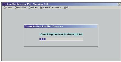
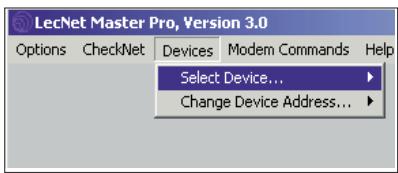
Fig. 3: Checking LecNet Addresses...
Fig. 4: Programming screen for the AS 8 / AS 8 TC.
Important!
4.2.3 Selecting Devices
In Remote mode, you can adjust all parameters from the computer. The settings you make on the computer will override the settings of the controls on the AS 8/AS 8 TC.
- In the "Remote Level Control" field, click on "Remote" and set the input gain for each channel.
- In the "Auto/Direct Mode control" field, click on "Remote" and click on either "D for direct mode or "A" for automatic control for each channel.
Set any channels that you use for audio sources or an announcement microphone to "D".
- In the "Comp/Lev Control" field, click on "Remote" and "C/L In" to switch the compressor/leveller in.
Use the arrow buttons below "Thr" to set the compression threshold. We recommend setting the threshold to -12 dB or lower. - The "Channel Section" part of the screen shows the status and signal level of each channel.
To display additional information, click on one of the keys "Ch1" to "Ch8" at bottom right, for instance, "Ch1". The "Channel x" field will indicate the Channel Level, Channel Attenuation, and Channel Remote Level of the selected channel (in this example, "Channel 1").
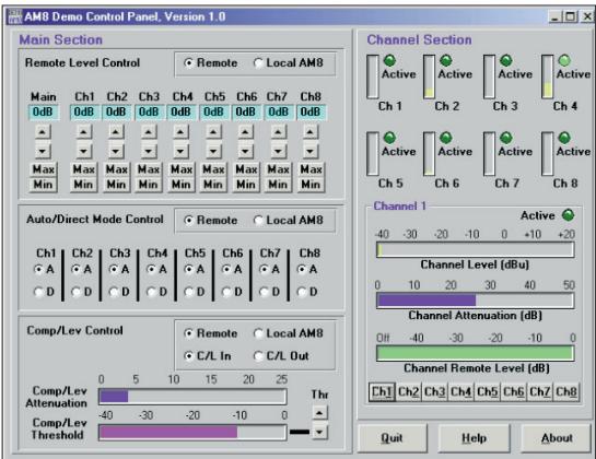
Fig. 5: Parameter and metering screen.
4.2.4 Adjusting Parameters
The front panel LEVEL controls remain active in "Remote" mode, although their range is limited.
5. Save your settings by clicking on "Quit" and answering the questions appearing on the screen with "Yes" or "No".
The external controls you may have connected to the AS 8 / AS 8 TC allow you to adjust the signal level of or mute the appropriate channels.
The external controls are always active, no matter whether the AS 8 / AS 8 TC is in "Local" or "Remote" mode.

4.3 Remote Level Controls
1.1 Sécurité
3.1 Montaggio in rack
H A Harman International Company.
AKG Acoustics GmbH
Lemböckgasse 21-25, P.O.B. 158, A-1230 Vienna/AUSTRIA, Tel: (43 1) 86 654-0*, Fax: (43 1) 86 654-7516, http://www.akg.com, e-mail: sales@akg.com
AKG Acoustics GmbH
Bodensestraße 228, D-81243 München/GERMANY, Tel: (089) 87 16-0, Fax: (089) 87 16-200, http://www.akg-acoustics.de, e-mail: info@akg-acoustics.de
AKG ACOUSTICS, U.S.
914 Airpark Center Drive, Nashville, TN 37217, U.S.A., Tel: (615) 620-3800, Fax: (615) 620-3875, http://www.akgusa.com, e-mail: akgusa@harman.com
- Safety
- Environment
- Description
- Introduction
- Packing List
- Installation and Interfacing
- Rack Mounting
- Daisy Chaining
- Audio Connections
- Connecting to the Computer
- Connecting Remote Level Controls
- Operating Notes
- Local Mode
- Remote Mode (Computer Control)
- Setting Up your Software
- Selecting Devices
- Adjusting Parameters
- Sécurité
- Montaggio in rack
Brand : AKG
Model : AS 8 TC
Category : Professional audio equipment